|
Staring uModbus(m):
Once uModbus(m) has been installed and started the first screen you will see is:
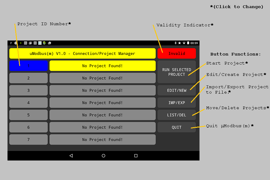
From here MODBUS project profiles can be created, managed and launched and at any one time
up to 100 profiles may be made available. Out of these 7 may be selected for quick launch
and placed on this screen.
On each line the name of the project profile is shown to make easy selection possible. If it is the first time the program had be ran all 7 lines will say “No Project Found!"
Each project profile can be given a number of 1 to 100 and it is this number that is shown
in the left hand column of the quick launch screen. The project profiles that are shown
on this quick launch list can be simply changed by pressing the numbers down the left
hand side, for each location on the list any project number may be selected.
If a project profile is valid and can be launched this is shown in the top right hand
corner in green, to begin with no valid profiles are ready so we need to create one.
Creating a new project profile :
To create a new project select any line on the quick launch screen and press new/edit, the screen
should then change to:
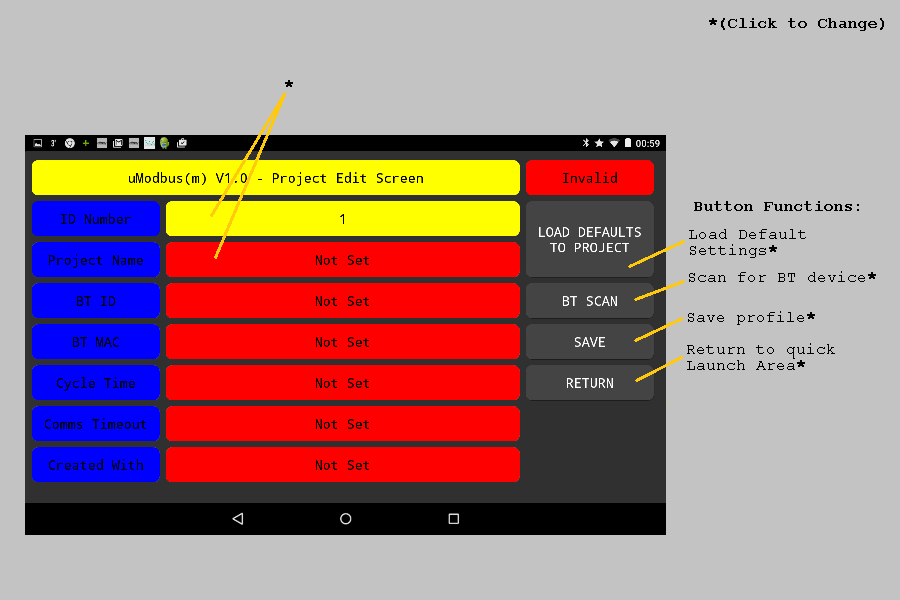
If the line was unused then you can start to build your project profile striate away, if however it was occupied first change the ID number to one that is currently unused.
To build your project profile follow the steps below:
- Change the ID number
(if required)
- Enter a project name
- Press load defaults
(this will load standard values into the communications scan and timeout cells)
- Press BT scan to find the Bluetooth slave associated with the MODBUS task
(if this is the first time that the Bluetooth device has been used then it
will need to be paired with your device, by default most Bluetooth devices
user “1234” or “0000” as a pair code)
- Save the project profile and return back to the launch screen
Once populated the screen will look something like this:
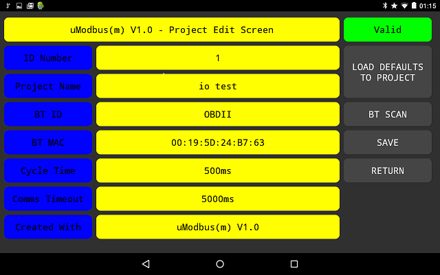
and on selecting return your new entry should appear in the list:
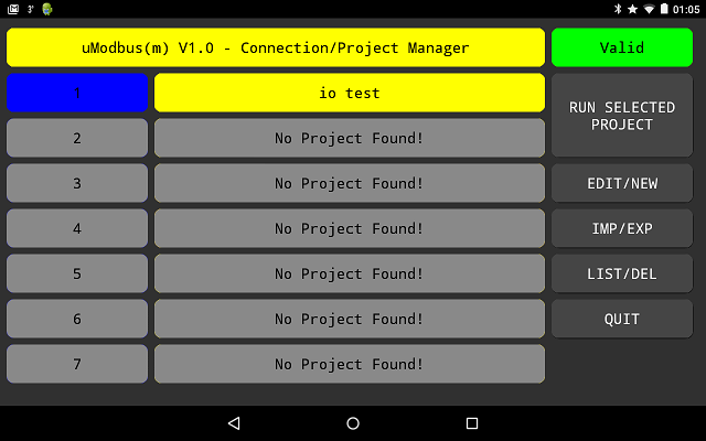
If your new profile dose not appear on the list then one of the entries on the quick launch screen must be changed so that it points to your new project profile, to do this touch one of the ID numbers down the left hand side and change it to the ID of your new profile.
Once your profile appears on the quick launch list then the top right hand indicator should
go green to show all the correct parameters have been entered successfully. The communications baud rate and parity settings will depend on your Bluetooth device and the manual for your device should be consulted if you are unsure what these are.
You are now ready to quick launch into your MODBUS communications task.
Making alterations to the MODBUS task:
Once the MODBUS task is launched then the screen will change to the following:
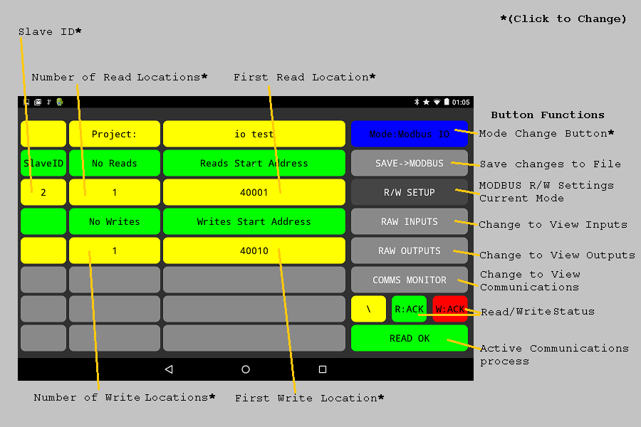
If all is well and the MODBUS slave is responding to read requests then you should hear a system message stating that the MODBUS link has been established.
The important factors to consider here is that the Slave address is correct (otherwise the remote slave will not respond) and the read and write locations are valid for your device (valid locations for MODBUS usually range fro 40001 to 49999 for the functions used).
Initially the read and write locations are 40001 for Read and 40010 for Write, but these can be changed to anything within the valid range.
The maximum number of reads permitted is upto a block size of 8, but again initially this is set to one.
The highest number of writes permitted is again upto a maximum of 8, but this may be reduced to zero. This is unlike the read setting as at least one word read is required to maintain the communications poll to the MODBUS slave.
Reading Inputs:
Once communications with the MODBUS slave has been established the result of the MODBUS reads may be viewed by pressing the Raw Inputs button, on selection the screen should change as below. The number of lines displayed will depend on the number of read locations selected on the MODBUS R/W Setup page. Both the integer and binary versions of the returned values are displayed on this screen.
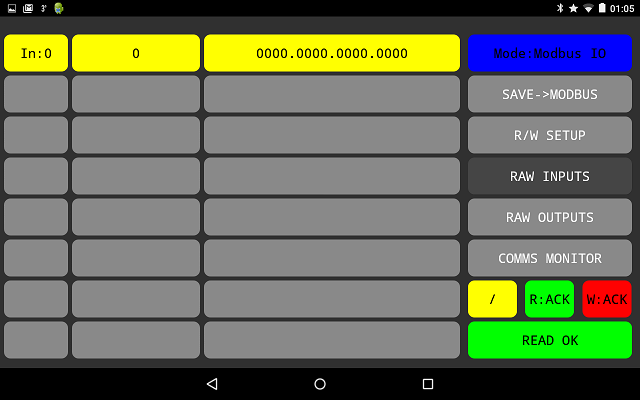
Here if we know the start address of the block read, the line numbers can be related to the source location from where the data was read. For example if 4 read registers were selected starting at 40001 then the display lines correspond to the source registers as below:
In:0 = 40001
In:1 = 40002
In:2 = 40003
In:3 = 40004
Writing Outputs:
If any MODBUS write locations have been selected on the MODBUS R/W Setup page then by selecting the Raw Outputs button a number of MODBUS write locations will be displayed as below:
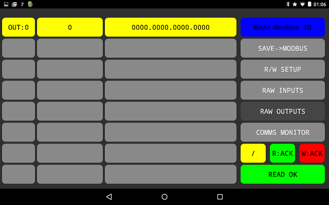
Again both the integer and binary representations of the locations are displayed, however this time by touching the integer or binary representations the contents can be altered. On accepting the change the entered value is sent to the MODBUS slave.
Again the line number can be related to the final destination of the MODBUS write:
Out:0 = 40010
Out:1 = 40011
Out:2 = 40012
By selecting the integer representation a simple entry window allows the transmitted number to be changed, however if we select the binary representation the following window will open that allows a bit by bit alteration of the transmitted word:
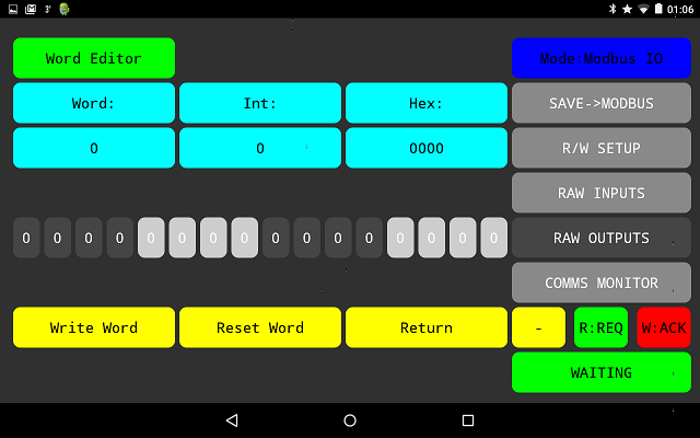
Here the entered binary representation of the transmit word are depicted in both integer and hexadecimal form, once the required alteration to the word is made various options are available as the word could be written to the the salve, reset to before any alterations were made or we can return back to the Raw Output word screen.
Checking Communications:
The last of the options on the MODBUS configuration page is Comms Monitor, this simply allows the communication traffic between the master and the slave to be monitored.
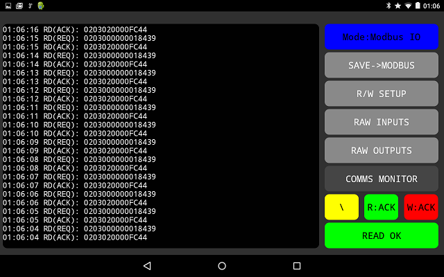
Changing Software Options:
Finally some basic software options may be viewed and modified, this screen can be accessed by pressing the mode change button and selecting Options&Setting from the list.
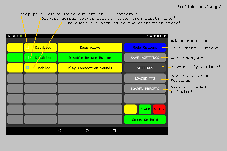
These functions serve specific purposes and these are listed below:
Keep Alive - This has been included as most android device go into power save if the screen is
not pressed for a period of time. By selecting this function and saving the changes.
The phone will not goto sleep while the program is running. If uMODBUS(m) is quit then
this function is released and the android device will be able to sleep normally again.
Also if the battery drops to below 30% then this function is again released.
Disable Return Button - This has been added as on some devices the return button (sometime
represented by an arrow folding back upon itself) can be easily accidentally pressed quitting
the communications program.
Play Connection Sounds - With this function selected (this is selected by default) the
communications state of the program are announced to the user.
|